This topic was already covered somewhat in an earlier post (click here to revisit), but at least I will reoffer the salient points with updates where necessary, and some images.
First the boards must be joined by means of a hinge which is strong and flexible. I followed the general idea of Bruce Newman’s method, seen here
Hinging pneumatics
Once hinged, time to recover. Your cloth of choice, with appropriate adhesive, and sharp scissors are the order of the day. I was fortunate to be able to get traditional thin rubberized cotton cloth, which was of course mounted with hide glue. The future availability of this cloth is in question, at the time of this publication.
As with other operations, it is a matter of getting the glue exactly where you need it, and avoiding it where you do not, using just the right amount. Experience will show you the way.
Recovering pneumatics, front and sidesRecovering pneumatics, tail sections. One elastic keeps the pneumatic from closing completely (there are no cloth spacers inside), another elastic clamps the front of the pneumatic so that it does not dry in the “hingebound” position
If you have done good work, the cloth (and the glue joint) will form an airtight seal around the perimeter of the pneumatic. It is still advisable to renew the sealer on the top face of the moveable board, and the exposed “overhang” section of the stationary board. Some rebuilders choose to seal the insides of the boards, before recovering. I chose to do it last, after the hangers had been reattached. As Bruce Newman put it, this way also provides extra “insurance” around the glue joint, especially at the corners of the boards where it can be a little tricky. Obviously, we do not want to get shellac sealant on the newly applied cloth, so work carefully!
Pneumatics recovery in various stages of progress
And so too with previous operations, uniformity is very much desired to assure consistent performance. If your first few attempts are not great (as mine were), take them apart and redo them. You will be happier in the long run. The pneumatics (along with the other bellows in the motor and pump) are under constant repetitive use, so attention to detail is paramount. Take the time to get it right!
Pneumatics recovery finished, assembled for remounting on decks
Test your work by closing each pneumatic, plugging the hole and trying to pull open, you should feel stiff resistance to moderate pressure (admittedly, it is awkward to do this step). If all your pneumatics are tight, onward to the next phase.
Once the boards have been removed from the decks, there are several operations to prepare them for rebuilding the pneumatics – this assumes you are reusing the old boards, as I did.
The old cloth must be removed from the boards. There are “dry” and “wet” options. Dry involves using a belt sander or manual scraping. Wet involves submersing the boards in simmering water for a short time, until the glue dissolves. Still some others advocate putting the boards in a microwave oven to destroy the glue joint, without scorching the wood.
Each method has its advantages; I opted for the wet method which ensured that the cloth came off with very little manual effort and with zero loss of wood surface. The disadvantage is that this method is rather messy. A critical caveat with using water with wood boards is that the boards must be placed to dry in such a way that the air reaches as much of the surface area as possible. If the wet boards are placed flat on one side, they will cup or warp, and potentially ruin them for reuse.
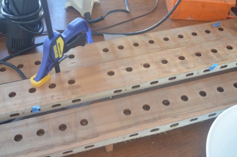
Here is what I came up with, using a kitchen grilling rack to hold the boards nearly upright so that the majority of the surface is exposed and the faces dry at an equal rate.
Drying the wet striker pneumatic boards, so that all long sides are exposed to air
Once clean and dry, the boards must be repaired. In my case there were a fair subset which were cracked along the long grain when they were pried off the deck. These cracks must be repaired with glue to restore the structural integrity of the boards. It does not have to be fancy, just effective. I had a box of binder clamps on hand from the office supply store which served well.
single pneumatic boards drying after glue repair
Finally, the boards must be surfaced. Since I used the water method, everything came out rather clean in the end, however I did want to make sure the face of the stationary board was quite smooth in order to form a good joint back onto the deck. And of course the repaired boards may have had residual glue on them as well, so a very light, even and quick pass on the belt sander took care of this nicely. Don’t overdo it with the belt sander! Once boards are all prepped, it’s time to turn them back into pneumatics!
After all the boards have come off, examine each deck and determine what work is needed to clean it up.
In a best case scenario, the deck board surface just needs a light sanding, to take down the grain and smooth out any minor high spots. You should not need to sand enough to degrade the scribe lines indicating the positions of the pneumatics.
If, in the course of removing pneumatics, you gouged or otherwise damaged the surface, you will have to repair as best as can be done. Minor voids can be filled with hide glue when the pneumatic is set down; moderate damage will need to be repaired. If you have numbered your boards, and if large splinters remained attached to the pneumatic boards, it should be possible to steam off these splinters then reglue them to their original positions on the deck board. This is all quite tedious, so best prevented in the first place, by careful removal.
A less successful attempt at removing the last board caused gouges in the deck.
Thankfully the chips can be reglued to the deck with not much extra workOther small repairs to the deck, in progress, with small pieces glued and clamped with painter’s tape
If you know there will be a good amount of time elapsing before you will be regluing pneumatics (as was the case with me), it is a good idea to number each spot in pencil, to make the reassembly more smooth.
Now is also a good time to renew the sealer inside the channels of the decks. Thick sealing shellac is the traditional choice and will ensure each channel is independently airtight, which is a must for a well functioning action.
Finally, the front edge of each deck (which connects to the secondary valve board) probably has a gasket in place. Remove the gasket, surface the deck edge as necessary. Measure and cut new gaskets, but it’s better to not apply them until after the pneumatics have been first been glued down, to reduce the chance of getting glue on the new gaskets.
With the lift rods and fingers detached, it should now be easier to see how the decks are attached to one another, and work from there to separate them. In the case of my action there are 3 tiers, with the bottom and top decks screwed to the middle, as well as having metal brackets which support the 3 tiers together on the front face.
Old striker pneumatics on their decks, ready for dismantle process
Here is a bullet pointed list of operations, which I developed for this process:
• Check tightness of larger block screws, before removal • Measure span and overhang of striker pneumatics (if not already done) • Number pneumatics (mark or stamp on bottom, with system of choice) • Separate decks, set support blocks and screws aside (clearly identify number and orientation of each deck and block!) • Slit open pneumatics and fold back; number both boards inside (with the inside number of the moveable board visible through the hole of the stationary board, ideally) • Remove moveable boards and excess cloth and hinge material from stationary board • Remove metal hangers or wood fingers from moveable board, set aside and keep in order if possible! • Remove the stationary boards from their decks
Most of the operations on the above list are tedious but straightforward. The more organized and methodical you are, the more you will thank yourself later.
If the boards have metal hangers, these are normally attached with 2 screws and reinforced with thick shellac. After removing the screws they should come free with a sharp twist. If there are hardwood fingers on the boards, exercise caution but the principle is the same. If the board and finger are integrated, you will have to work around them as you rebuild.
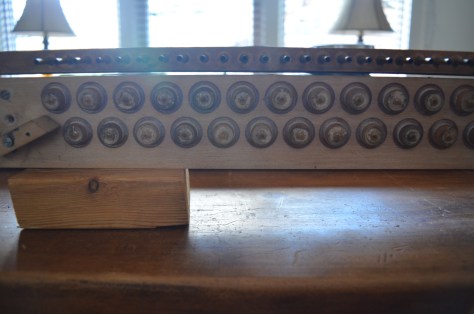
View of striker pneumatics after separation of decks.
Now to remove the metal hangers from each top board
Removing boards from the pneumatic decks can be an exercise in drudgery and frustration, especially the first time you do it. Different rebuilders take different approaches, and the decision is also informed by whether you plan on keeping the original boards, or not. In my case I did, so I had to be quite patient and persistent in getting the boards off with as little damage as possible to them or the decks.
The main thing, before getting started, is to index the board positions on the deck, so the boards go back exactly where they came from – this is important!
To repeat, getting the boards to come off relatively cleanly can be a challenge, particularly if they are not original and a synthetic glue was used. Try using different tools and changing your technique and angle of attack, to see what works best.
Once the removal is all done, it’s time to survey the damage and proceed accordingly.
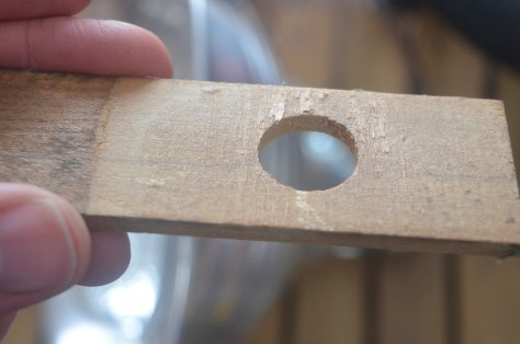
Pneumatics separated and stationary boards numbered. The indexing lines are marked along the sides and back of the boards with a sharp instrument like a utility knife. Try to break away any old glue beads along the sides and inside the port hole of the boards, before attempting to pry them off. Beginning process of removing boards (a dry chisel technique, in this case). If one board is rather stubborn, try moving on to the next, which will give more space to attack from a different angleThis board has come off as cleanly as can be expected, and will just need a light sanding to finish.
The old hide glue joint was broken the right way, to allow the board to come off with minimal damage.
The foundation of the stack is the assembly of pneumatic decks and striking fingers. As previously mentioned, this assembly can be separated as a whole from the secondary valve chest, and then broken down into its constituent components.
While this series of operations is not rocket surgery it is surely among the longest and dirtiest jobs of the entire restoration: you have a lot of work ahead of you!
Before starting the teardown in earnest, it’s a good idea to take photographs from different angles and different distances, to document how the parts looked before you took them all apart. And a reminder to make note of key measurements such as span and overhang of the striker pneumatics, the average position of the leather nuts on the striker finger lift rods, and indexing all support blocks (position/orientation) before removing them from the decks.
The first order of business is to disengage and remove the striker finger lift rods from the pneumatic hangers, or whatever similar arrangement is necessary in your particular action.
Prior to disassembly
This usually involves removing the lower leather nut from the threaded lift rod, to then free it from the metal hanger or wood finger. If the nuts are extremely old, they may be crushed with pliers. If they are moderately old, you should be able to back them off with a simple custom tool that can be made with thin metal tube stock. John Tuttle has instructions here, and this is how my version came out:
leather nut driving tool, made from brass tube stock
Since you are in the teardown stage, there is not an enormous amount of care needed to remove the nuts. By contrast, when it comes time to replace new nuts on your finished pneumatic decks, extreme care must be taken!
But let us not get ahead of ourselves, for now just get them off as best as can. If corrosion has set in at the joint of the nut and rod, you will likely need pliers to break the joint and get them started.
Removing striker finger push rods
Once that is done, and the rods are disconnected, if it is possible to do so, disconnect the rods from the striker fingers, and store them, keeping them in order if possible. A sheet of boxboard will suffice. They can be cleaned and polished later.
Turn your attention to the striker fingers. Number them, make note of any damage or stripped screw holes in the deck, as well as the condition of the bushings, and then remove them. If the fingers have a glue joint to the deck underneath, a firm but careful blow with a block of the same thickness should free them with minimal damage.
a striker finger removed from the pneumatic deck
Set aside the fingers and screws, the screws do not really need to be kept in order, as they are all theoretically the same. Like the rods, the fingers will need a good cleaning and lubrication before remounting.
Finally, if there is a finger rest rail along the top of the pneumatics, make note of measurements and orientation; index it if necessary, then remove it from the deck. Be aware that there may be screws hidden under the layer of felt atop the rail. Remove the felt but make note of the thickness of this material, as it will save much trouble to duplicate it as closely as possible.
Reassembling the primary chest should be fairly straightforward; the hardest part may be remembering the orientation of the boards, if they have all been apart for some time!
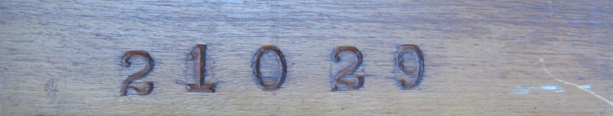
When I first removed the player action I had noticed that the bass end was stamped with a serial number on each board component, and I wondered why. Now, having to put all the pieces back together, I realize the numbers are a guide to help you get things oriented correctly!
Bass end of primary chest stamped with serial number reassembling primary chestafter being separated for quite some time, the components of the primary chest needed some coaxing to join back together tightly.
Once you got it all put together, let’s test the chest! As with the other test, hook up your suction source securely. Tape off both the row of input nipples, and the output channel holes (bottom of L board) Activate suction and first listen that all valves are seated properly (with no leaks) in the off position. Compare the suction level in the closed chest with what you had calibrated on a blocked feed. There should be very minimal loss at most.
Next unblock each nipple one at a time, as well as its corresponding output hole at the L board. Each valve should repeat quickly and reliably. Remember that the primary valve is an “outside” valve and has opposite signal pattern from the secondary “inside” valve. In other words, when you uncover the input nipple, you introduce atmosphere to activate the valve, which closes the suction feed and sends atmosphere to the output. In still other words, when the nipple is uncovered, you should hear nothing at the output hole. You will still hear a small hissing leak from the nipple, because the bleed permits the suction to pass through.
The valve design is simple, so if there are problems, it may point to unsatisfactory work such as having gotten glue on the valve facing (preventing it from seating), or a pouch which has not been sealed enough, or a blocked bleed, etc. Examine the signs and diagnose accordingly. In my case I had been a little too zealous with sealant application in the L board channels, so I had a couple of channels which had become blocked and had to be unclogged.
Once the primary chest is working well, attach the whole chest to the secondary chest, and test cumulatively. Now with the primary valves and bleeds in the equation, the secondary valves should repeat with as much rapidity as you can physically actuate, at least 10 times per second.
If you have problems: Go through a logical troubleshooting procedure to source the issue. Now is the time, don’t delay!
The remaining components of the primary valve chest are the so called “L board” (owing to its shape) and the nipple board.
The L board can in fact be disassembled further into 2 separate boards, in most cases, in order to replace the gasket that is sandwiched in between, and to make renewing the sealer in the channels easier.
Basically, the operations on these pieces are the same:
Make sure the interior channels of the boards are well sealed, including the junction of the brass nipples in the nipple board
Replace the gaskets on the interior facings of the boards
I have discussed these operations already, so here are just a couple of images from the process as I did it:
removing old leather gaskets from L board and nipple boardmarking new gaskets (neoprene) before punching and gluing
Since I have recently discussed the secondary pouch board, I will endeavor to avoid redundancy and keep it short for this post.
The main difference with a primary pouch board is that it will have a row of “bleeds”; brass cups which bleed a tiny amount of suction back into the area underneath the pouch, to ensure prompt resetting of the valve after the atmosphere signal is cut off.
The bleed cups may be in good condition, or they may be tarnished or even corroded. If they are damaged or corroded, they should be replaced; if they are simply cosmetically tarnished, then the main thing is to ensure that the bleed hole is clear and functional, and that the seal around the cup is still good.
The bleeds are indicated by the green arrow in the following image:
Primary pouch board, foreground
The red arrow indicates that the last pouch is lifting away from the board, at its edge. Check the pouches for damage or lifting such as this, and repair accordingly.
As with the secondary, check that the pouches are tight (covering each bleed in turn), and that the channels are all sealed independently.
I have already talked about primary valves here; as well as the fact that (in a common double valve player stack) the primary board takes the “input” signal from the tracker bar hole, and amplifies it to the secondary valve chest.
The primary valves are simpler in design than their secondary counterparts, but just as important to restore correctly.
To dismantle the common style primary valve board, support the board with two other lengths of lumber (e.g. 2×4″ or similar), placed on the underside edges so that the bottom of the valves have a couple of inches of space underneath them.
Now you can go through and hit each valve top with a sharp and firm blow (but not too strong!), striking them with a small flat hammer or with a punch equal in diameter to the valve stem (driven by a hammer).
This should cleanly break the glue joint of the stem to the top of the valve, without causing damage to either (assuming the glue is old hot hide glue). The glue joint here is quite small.
Once the joints are all broken, remove the leather facings and clean all the valve facing surfaces. Here is an image of that work in progress:
primary valve board teardown
It is advisable to keep pairs of valve buttons (upper and lower) together. The surface must be kept true, so don’t go overboard with the sanding, when lapping the surfaces. You need just enough to keep the surface true without making it mirror smooth, otherwise you are reducing the effectiveness of the new glue joint. A medium grit sandpaper like 120 should do just fine.
Using hot glue, glue all the new facings onto the valves, without getting any glue on the business side of the facings, this is important! Also important is to preserve the flatness of the facing surface, so it’s a good idea to press the surface onto plate glass or another dead flat surface immediately after the leather is glued.
Some primary valves (like mine) have cloth washers on the lower part of the valve, underneath the leather facing. It is probably a good idea to replace these (if they are in bad condition), simply because you will alter the valve to pouch gap if you remove these washers. I used a circular punch set (very handy tool for player work) to make a new set of cloth washers, as seen here:
punching and installing new cloth washers (old washers on the left, new washers on the right)
Once the valve parts are ready, set them aside for the moment.
Turn your attention to the board itself, checking that the top and bottom are still true and there is no damage or problems with the board. If warranted, reseal the interior channels with shellac, being careful to not get any on the valve contact surfaces.
Now it’s just a matter of regluing the valves back in place, with the right gap. This gap in most cases is 1/32″ or 0.79mm. You can make a regulation gauge tool from different rigid materials; John Tuttle’s suggestion was to make one from an ivory tail, so that’s what I did!
primary valve gluing: “before” image
Before you begin the glue up, quickly check each valve pair that the top does not grip the stem too tightly (a little too loose is actually okay). If too tight, you risk having the leather stay compressed when you press the valve together, giving you a false reading on the gap. Too little gap will starve the valve. Consistency is important as always!
Reglue the valves, putting just a tiny dollop of glue on top of each valve stem, so it spreads to make a small bead around the stem on the top piece. It really doesn’t need to be a lot!
Using your gauge, insert it under the upper facing, and press the valve together lightly for several seconds. Done! On to the next one. As long as you are consistent in applying pressure with your hand, your valves should all come out to be the same gap.
primary valve gluing: “after” image, with gap regulated by gauge
Once he glue has cured completely, go back and test each one with the gauge. The valves should all accept the gauge freely, and offer the same amount of resistance when withdrawing the gauge. If there are noticeable outliers, break the joint and reglue with more care.
One last thing is to replace any gaskets on the underside of the valve board, which will contact the pouch board.
Following on the previous posts, both the valve board and pouch board have been rebuilt or refurbished for optimal performance. Now it is time to test your work, to see how it performs. This will be a lengthy post with several steps, but stick with it!
To bench test the valve chest, you will need a suction source. Although it is possible to generate a decent amount of suction with the human lungs for a short period, it is much better to have an electric powered suction machine. In order of preference, the following devices can work: 1) reproducing piano rotary pump with electric motor; 2) player piano generic suction box, of the “PP Co” type 3) small shop vacuum cleaner, available at big box stores.
It is also important to have an instrument to measure the suction level (e.g. a vacuum gauge), so that you know you have enough suction power, but not too much (so as not to damage your work – a possibility with a vacuum cleaner).
Assemble your secondary chest and devise a way to hook up suction in a secure and leak free way to the chest. In my case, I took a scrap piece of hardwood and made a junction block, which could be attached to the suction hose and then clamped to the intake port of the chest. It doesn’t have to be fancy, just so long as it does what it needs to do.
Test flange block to connect suction box to valve chest. The green colour indicates interior “T” channel with through hole to gasketed bottom face, and a nipple on the side to connect vacuum gauge. The 2 other holes in the side are sealed off and not relevant.
The suction source should be set to a low-ish setting (7-10 inch water column) and the vacuum gauge also needs to be in the mix to measure what you have.
Depending on if the chest is a single or double valve model, testing procedure will vary. For my double valve chest, I taped off the ouch board edge with the input holes, with pieces of tape covering 3 holes per piece.
Preparing to test the lower (inside) valve facings.
Note that only the screw holes on the top face of the board are taped off for this first test.
The pneumatic port holes (oval) will be taped off for a later test of the outer facings.
First, with all input holes taped, we want to be sure all the valves are off, and seated so that there is no leakage.
This is also the time to calibrate the overall tightness of the chest; having measured prior the suction level on the gauge with the hose completely stopped by hand (before hooking up to the chest), now look at the gauge again and compare. In a perfect world, there is no difference in the gauge. In practical terms, however, a good target to strive for is a 1-2″reduction only in suction level. More loss than 2″ and you may have a problem with leakage, which will have to be found and corrected.
Let us return to the valves. With all the valves “off”, first pass your ear over the face of the valve chest to listen for any obvious hissing sounds. If you have difficulty hearing (if the suction machine is too noisy), try using a piece of tracker tubing, placing one end in your ear (not too hard!), and the other in the pneumatic channel which is next to each valve. This allows you to get right down to the seat plate, to hear any potential leakage. If the vacuum level drop is significant (no measurement) and you hear no audible leakage, it may be so severe and diffuse that you have to take a step back to diagnose the problem. In troubleshooting, we must use the process of elimination. You could start by taping a strip of airtight material over the whole top of the valve board, taking the valves out of the equation and evaluating only envelope of the chest and the perimeter gasket.
If that checks out okay, but still hear leakage problems, return to the valves and consider the following points (most common errors), which were compiled by Tim Gautreaux (from MMD):
the “inside valve” has been pressed too hard between the retaining collars and cannot flex [wobble] and seat against the metal plate;
the buttons are not screwed down enough and the pouches are holding the valves open [insufficient button clearance];
the pouches, if old, have shrunken and are holding the valves open;
the metal seats haven’t been sealed properly;
the metal seats haven’t been cleaned and coated;
the valves have too much or too little travel;
all the felt from the fiber [stem] guides is gone;
the gasket in the L-shaped board has not been replaced.
Once you believe that you have eliminated these potential problems (including the often overlooked issue of “wobble”), fire up the suction box again take a fresh look. To reiterate, when the valves are off there should be no explicit hissing or leak at the valve seat. The vacuum level loss should be minimal.
If these conditions are met, we must now repeat the test, but with the valves in the on position (pouches up). Before starting this test, tape or cover over the pneumatic channel ports and screw holes, and open all the pouch input channels. Turn on the suction, and again listed for the telltale hissing leaks. This time we are listening right at the top seat of the valve well, which is essentially at the outer holes on top of the valve board. With all valves open or “up”, with all other holes and ports on top of the valve board taped off or sealed, there should again be no audible hiss.
You can get the “big picture” by opening them all at once, but it is also valuable to test them one by one in sequence, actuating them as quickly as possible and stopping in both the on and off positions. It is undeniably tedious to go back and correct faulty valves, and some valve designs are worse than others for this.
However, this is the best time to do it, and it is absolutely necessary to correct errors as soon as they are noticed. This round of testing is just the first of several cumulative tests to be performed, and you can’t build good work on a bad foundation – it’s really that simple!
Once these valves are all working well, and your chest is tight, as a final test you should even be able to test this with your mouth by connecting a 3/4″ (or larger) hose and trying to suck the atmosphere out of the chest. With a big huff, you should encounter fairly immediate and significant resistance. The longer you are able to hold suction with the same amount of force, is a good indicator of how tight your chest is!
Upon successful completion of this work, you have achieved a nice milestone in your restoration. Congratulations! Now set aside the secondary chest, and get back to work!