Primary Chest reassembly + Testing (Round 2)

Reassembling the primary chest should be fairly straightforward; the hardest part may be remembering the orientation of the boards, if they have all been apart for some time!

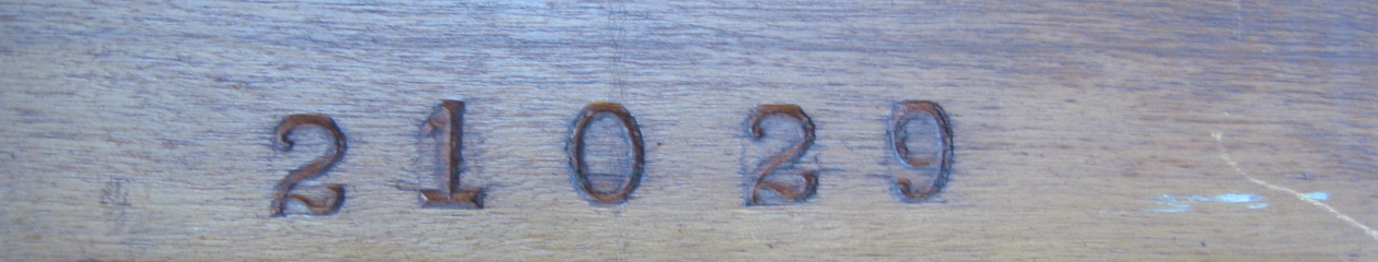
When I first removed the player action I had noticed that the bass end was stamped with a serial number on each board component, and I wondered why. Now, having to put all the pieces back together, I realize the numbers are a guide to help you get things oriented correctly!

Bass end of primary chest stamped with serial number
reassembling primary chest
after being separated for quite some time, the components of the primary chest needed some coaxing to join back together tightly.

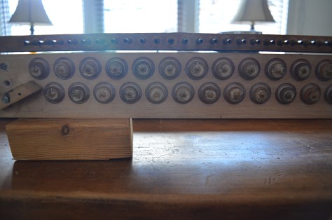
Once you got it all put together, let’s test the chest!
As with the other test, hook up your suction source securely.
Tape off both the row of input nipples, and the output channel holes (bottom of L board)
Activate suction and first listen that all valves are seated properly (with no leaks) in the off position.
Compare the suction level in the closed chest with what you had calibrated on a blocked feed.
There should be very minimal loss at most.

Next unblock each nipple one at a time, as well as its corresponding output hole at the L board.
Each valve should repeat quickly and reliably.
Remember that the primary valve is an “outside” valve and has opposite signal pattern from the secondary “inside” valve.
In other words, when you uncover the input nipple, you introduce atmosphere to activate the valve, which closes the suction feed and sends atmosphere to the output.
In still other words, when the nipple is uncovered, you should hear nothing at the output hole.
You will still hear a small hissing leak from the nipple, because the bleed permits the suction to pass through.

The valve design is simple, so if there are problems, it may point to unsatisfactory work such as having gotten glue on the valve facing (preventing it from seating), or a pouch which has not been sealed enough, or a blocked bleed, etc.
Examine the signs and diagnose accordingly.
In my case I had been a little too zealous with sealant application in the L board channels, so I had a couple of channels which had become blocked and had to be unclogged.

Once the primary chest is working well, attach the whole chest to the secondary chest, and test cumulatively. Now with the primary valves and bleeds in the equation, the secondary valves should repeat with as much rapidity as you can physically actuate, at least 10 times per second.

If you have problems: Go through a logical troubleshooting procedure to source the issue. Now is the time, don’t delay!

Primary L board and Nipple board

The remaining components of the primary valve chest are the so called “L board” (owing to its shape) and the nipple board.

The L board can in fact be disassembled further into 2 separate boards, in most cases, in order to replace the gasket that is sandwiched in between, and to make renewing the sealer in the channels easier.

Basically, the operations on these pieces are the same:

  1. Make sure the interior channels of the boards are well sealed, including the junction of the brass nipples in the nipple board
  2. Replace the gaskets on the interior facings of the boards

I have discussed these operations already, so here are just a couple of images from the process as I did it:

removing old leather gaskets from L board and nipple board
marking new gaskets (neoprene) before punching and gluing

primary pouch board

Since I have recently discussed the secondary pouch board, I will endeavor to avoid redundancy and keep it short for this post.

The main difference with a primary pouch board is that it will have a row of “bleeds”; brass cups which bleed a tiny amount of suction back into the area underneath the pouch, to ensure prompt resetting of the valve after the atmosphere signal is cut off.

The bleed cups may be in good condition, or they may be tarnished or even corroded.
If they are damaged or corroded, they should be replaced; if they are simply cosmetically tarnished, then the main thing is to ensure that the bleed hole is clear and functional, and that the seal around the cup is still good.

The bleeds are indicated by the green arrow in the following image:

Primary pouch board, foreground

The red arrow indicates that the last pouch is lifting away from the board, at its edge.
Check the pouches for damage or lifting such as this, and repair accordingly.

As with the secondary, check that the pouches are tight (covering each bleed in turn), and that the channels are all sealed independently.

Primary valve board

I have already talked about primary valves here; as well as the fact that (in a common double valve player stack) the primary board takes the “input” signal from the tracker bar hole, and amplifies it to the secondary valve chest.

The primary valves are simpler in design than their secondary counterparts, but just as important to restore correctly.

To dismantle the common style primary valve board, support the board with two other lengths of lumber (e.g. 2×4″ or similar), placed on the underside edges so that the bottom of the valves have a couple of inches of space underneath them.

Now you can go through and hit each valve top with a sharp and firm blow (but not too strong!), striking them with a small flat hammer or with a punch equal in diameter to the valve stem (driven by a hammer).

This should cleanly break the glue joint of the stem to the top of the valve, without causing damage to either (assuming the glue is old hot hide glue). The glue joint here is quite small.

Once the joints are all broken, remove the leather facings and clean all the valve facing surfaces.
Here is an image of that work in progress:

primary valve board teardown

It is advisable to keep pairs of valve buttons (upper and lower) together.
The surface must be kept true, so don’t go overboard with the sanding, when lapping the surfaces. You need just enough to keep the surface true without making it mirror smooth, otherwise you are reducing the effectiveness of the new glue joint.
A medium grit sandpaper like 120 should do just fine.

Using hot glue, glue all the new facings onto the valves, without getting any glue on the business side of the facings, this is important!
Also important is to preserve the flatness of the facing surface, so it’s a good idea to press the surface onto plate glass or another dead flat surface immediately after the leather is glued.

Some primary valves (like mine) have cloth washers on the lower part of the valve, underneath the leather facing. It is probably a good idea to replace these (if they are in bad condition), simply because you will alter the valve to pouch gap if you remove these washers.
I used a circular punch set (very handy tool for player work) to make a new set of cloth washers, as seen here:

punching and installing new cloth washers (old washers on the left, new washers on the right)

Once the valve parts are ready, set them aside for the moment.

Turn your attention to the board itself, checking that the top and bottom are still true and there is no damage or problems with the board. If warranted, reseal the interior channels with shellac, being careful to not get any on the valve contact surfaces.

Now it’s just a matter of regluing the valves back in place, with the right gap. This gap in most cases is 1/32″ or 0.79mm. You can make a regulation gauge tool from different rigid materials; John Tuttle’s suggestion was to make one from an ivory tail, so that’s what I did!

primary valve gluing: “before” image

Before you begin the glue up, quickly check each valve pair that the top does not grip the stem too tightly (a little too loose is actually okay). If too tight, you risk having the leather stay compressed when you press the valve together, giving you a false reading on the gap.
Too little gap will starve the valve. Consistency is important as always!

Reglue the valves, putting just a tiny dollop of glue on top of each valve stem, so it spreads to make a small bead around the stem on the top piece. It really doesn’t need to be a lot!

Using your gauge, insert it under the upper facing, and press the valve together lightly for several seconds. Done! On to the next one. As long as you are consistent in applying pressure with your hand, your valves should all come out to be the same gap.

primary valve gluing: “after” image, with gap regulated by gauge

Once he glue has cured completely, go back and test each one with the gauge.
The valves should all accept the gauge freely, and offer the same amount of resistance when withdrawing the gauge. If there are noticeable outliers, break the joint and reglue with more care.

One last thing is to replace any gaskets on the underside of the valve board, which will contact the pouch board.

That’s all folks!